Access to external equipment via Parallel Printer Port Programable with delphi
Want to control external devices using a computer? Of great fun, especially with just a few lines of Delphi programs, we can turn on the lights, turn on the motor, set the robot arm or to access other electronic equipment.
Perhaps this paper can be quite nutritious snacks for the likes ngoprek Delphiers practical electronics, this is because we do not have to make a card I / 0 itself, but simply by using just a parallel printer port.
Parallel Printer Port
Port this one, certainly there on every computer. Reflected by its name, this time more parallel port used for printing business data. Actually, the program port can be used for anything else, because it has input / output (I / O) data.
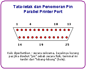
Layout of the twenty-five-pin (DB 25) parallel printer port, shown in Figure 1.
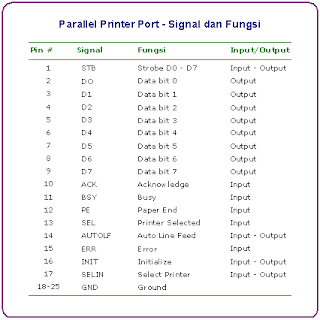
The signal table and function of each pin on the parallel printer port, shown in Figure 2. From there known pin 2 s / d 9 (signal D0-D7) serves as the output, which then can we use to control external equipment.
The Circuit
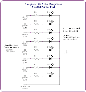
For the purposes of a second trial, we can connect the LED (Light emitting diode) through a resistor, output pins directly to the parallel printer port. It could also simply by measuring the voltage of 5 volts arise, when the data port in a high state.
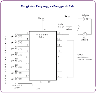
To be able to access a large burden and to prevent excessive loading on the parallel printer port, you should use a series of buffers (buffer).
From the scheme in Figure 4, visible pins 3,5,7,9,12,16 and 18
of the 74LS224 is connected to each relay. Next
switches on each relay is, can we use to
control equipment that has a big burden.
Delphi Program Code
Unlike Turbo Pascal or Delphi, where available functions 1 Port,
Delphi's 32 bit (version 2 s / d 6) that the function is not supported anymore.
Instead we use in-line assembler code.
Listing 1. Turn on the LED 5 from the circuit in Figure 3.
KirimDataKePort procedure (AlamatPort: Word; DataBit: Byte);
(* Address LPT1, range 378-37F hex
LPT2 address, range 278-37F hex
LPT3 address, range hex 3BC-3BF
see also the technical reference from Intel and Microsoft *)
asm
MOV DX, AlamatPort
MOV AL, DataBit
OUT DX, AL
end;
TForm1.btnLED5Click procedure (Sender: TObject);
begin
(* Sample calling KirimDataKePort procedures,
This will turn on the LED 5 (data bits-4 / 6 pin
of the circuit found in Figure 3. *)
KirimDataKePort ($ 378, $ 8); / / 00010000 binary
end;
In principle, to light the LED, we send binary data
8 bits to port. Customize this binary data transmission, with LED
who want lit.
For example, to light the first LED is 1 hex data
(binary; 0,000,001), whereas binary data 10,000,000
(80 hex / 128 dec) is used to light the LED eighth.
The following list, can be used as a reference.
DataPort Bit 0 = LED1 = 00000001 bin = 1 hex                                = 1 dec
                          DataPort Bit 1 = LED2 = 00000010 bin = 2 hex = 2                                dec
                          DataPort Bit 2 = LED3 = 00000100 bin = 4 hex = 4                                dec
                          DataPort Bit 3 = LED4 = 00001000 bin = 8 hex = 8                                dec
                          DataPort Bit 4 = LED5 = 00010000 bin = 10 hex =                                16 dec
                          DataPort Bit 5 = LED6 = 00100000 bin = 20 hex =                                32 dec
                          DataPort Bit 6 = LED7 = 01000000 bin = 40 hex =                                64 dec
                          DataPort Bit 7 = LED8 = 10000000 bin = 80 hex =                                128 dec
For those who want to experiment, Listing 2 is the program code
Application example from the controller as shown in Figure 5.
Listing 2. Controller application program code.
                          unit Unit1;

interface

uses
                                                                                                                                               Windows, Messages, SysUtils, Classes, Graphics, Controls,
                               Forms, Dialogs, Buttons, ExtCtrls, StdCtrls;
type
                                                            TForm1 = class(TForm)
                                 SpeedButton1: TSpeedButton;
                                 SpeedButton2: TSpeedButton;
                                 SpeedButton3: TSpeedButton;
                                 SpeedButton4: TSpeedButton;
                                 SpeedButton5: TSpeedButton;
                                 SpeedButton6: TSpeedButton;
                                 SpeedButton7: TSpeedButton;
                                 SpeedButton8: TSpeedButton;
                                 Bevel1: TBevel;
                                 Bevel2: TBevel;
                                 lblDataPortBit: TLabel;
                                 lblNoLED: TLabel;
                                 Label1: TLabel;
                                 Label2: TLabel;
                                 Label3: TLabel;
procedure                                  SpeedButton1Click(Sender: TObject);
procedure                                  FormCreate(Sender: TObject);
private
procedure                                                                 KirimDataKePort(DataPortBit: Byte);
public
                                                                { Public declarations }
end                               ;

var
                                                                                       Form1: TForm1;

implementation

                                                                                                                {$R *.DFM}

uses
                                                                                       Math;

const
                                                                                       AlamatPort = $378;

procedure                                                         TForm1.KirimDataKePort(DataPortBit: Byte);
var
                                                            Nilai: Byte;
begin
                                                            lblDataPortBit.Caption := IntToStr(DataPortBit);
                               lblNoLED.Caption := 'LED No. ' + IntToStr(DataPortBit + 1) +
                                                   ' Nyala';
                               Nilai := Trunc(Power(2, DataPortBit));
asm
                                                                MOV     DX, AlamatPort
                                 MOV     AL, Nilai
                                 OUT     DX, AL
end                               ;
end                             ;

procedure                                                         TForm1.SpeedButton1Click(Sender: TObject);
begin
                                                            (* Put the 8 pieces TSpeedButton, set propeti Tag
 of 8 with the value TSpeedButton
 0 to 7. From the Object Inspector,
 directed event Clik from all TSpeedButton
 the SpeedButon1Click. *)

                                                          KirimDataKePort((Sender as TSpeedButton).Tag);
end                             ;

procedure                                                         TForm1.FormCreate(Sender: TObject);
begin
                                                            KirimDataKePort(0);
end                             ;

end                                                        .


